|
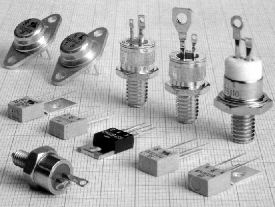
6. Thyristors, triacs, diacs There are several thyristors displayed on 6.1. Triacs look the same, while diacs look like small power rectifying diodes. Their symbols, and pin-out is found in figure 6.2.
A thyristor is an improved diode.
Besides anode (A) and cathode (k) it has another lead which is commonly
described as a gate (G), as found on picture 6.2a. The same way a diode
does, a thyristor conducts current when the anode is positive compared to
the cathode, but only if the voltage on the gate is positive and
sufficient current is flowing into the gate to turn on the device. When
a thyristor starts conducting current into the gate is of no importance and thyristor
can only be switched off by removing the current between anode and cathode. For
example, see figure 6.3. If S1 is closed, the thyristor will not conduct, and
the globe will not light. If S2 is closed for a very short time, the
globe will illuminate. To turn off the globe, S1 must be opened. Thyristors are marked in some
circuits as SCR, which is an acronym for Silicon Controlled
Rectifier.
6.1 Practical examples Picture 6.5 detects when light is present in a room. With no light, the photo-transistor does not conduct. When light is present, the photo-transistor conducts and the bell is activated. Turning off the light will not stop the alarm. The alarm is turned off via S1.
A circuit to flash a globe is shown in figure 6.6 This circuit flashes a 40w globe several times per second. Mains voltage is regulated using the 1N4004 diode. The 220u capacitor charges and its voltage rises. When this voltage reaches the design-voltage of the the diac (20v), the capacitor discharges through the diac and into the triac. This switches the triac on and lights the bulb for a very short period of time, after a period of time (set by the 100k pot), the capacitor is charged again, and the whole cycle repeats. The 1k trim pot sets the current level which is needed to trigger the triac.
A circuit to control the brightness of a globe or the speed of a motor is shown in figure 6.7
If the main use for this circuit is to control the brightness of a light
bulb, RS and CS are not
necessary. |