|
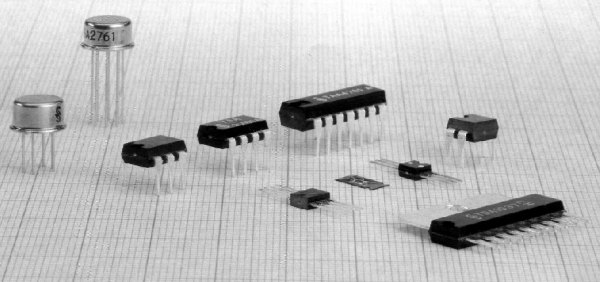
7. Integrated circuits Integrated Circuits play a very important part in electronics. Most are specially made for a specific task and contain up to thousands of transistors, diodes and resistors. Special purposes IC's such as audio-amplifiers, FM radios, logic blocks, regulators and even a whole micro computers in the form of a micro controller can be fitted inside a tiny package. Some of the simple Integrated Circuits are shown in figure 7.1.
Depending on the way they are manufactured, integrated circuits can
be divided into two groups: hybrid and monolithic. Hybrid circuits have
been around longer. If a transistor is opened, the crystal inside is very
small. This means a transistor
doesn't take up very much space and many of them can be fitted into a
single Integrated Circuit.
Most integrated Circuits are in a DIL package - Dual In Line, meaning
there are two rows of pins.
(DIL16 and DIL8 are shown in 7.2b and 7.2c). The device is viewed
from the top and the pins are numbered in an anti-clockwise direction. Figure 7.2i shows an operational amplifier. Signs + and - represent inverting
and non-inverting inputs. The signal to be amplified is applied
between one of the inputs and ground (ground and supply aren't
represented, but are necessary for the circuit to operate).
7.1 Analog integrated circuits While on the topic of analog circuits, we will look at the LM386 IC. It has all the components for a complete audio-amplifier. Figure 7.3a shows an example of an amplifier made with this integrated circuit, which can be used as a complete amplifier for a walkman, interphone, cassette player or some other audio device. It can also be used as a test circuit for troubleshooting.
The signal is brought to the
non-inverting input (between pin 3 and ground).
Inverting input (pin 2) is connected to ground. If 10µF is placed between
pins 1 and 8 a voltage amplification of 200 is created. If this capacitor
is removed the amplification is 20. It is possible to achieve in-between amplification by adding a resistor
and connecting it in series with the capacitor. 7.2 Digital integrated circuits The CD4011 will be our "show-and-tell" IC to cover
the main characteristics of digital circuits. It is a 14 pin DIL package.
The pin-out is shown in figure 7.4a. Note the
small half-round slit on one end of the IC. It identifies pin 1. Pins 7 and 14 connect
to a supply (battery or DC power supply). Negative is connected to
pin 7. Positive is connected to pin
14.
Logic circuits have many applications, but their main use is
in computer circuits.
Lets look at the functionalities of the following circuit. Both inputs of NI1 are connected to each other, so when input P is HIGH, output is zero. This logic zero is passed on to NI2, so no matter what is on the input 6, output 4 is logic one. This means that, between the ground and pin 4, the voltage is equal to 12V.
Fig. 7.5: Sensor switch using a 4011 Current flows through capacitor C
and resistor R, so capacitor begins to charge. Every uncharged capacitor behaves
like a short circuit. Because of that, when 12V appears on pin 4, it is
also present on resistor R and also on pins 8 and 9. Pin 10 shows
logic zero because of this which is connected to pin 6. From now on, logic
zero on pin 5 is no longer needed because only one input needs to be zero
for the output to be logic one. So input P is no longer needed. Gates
NI2 and NI3 maintain logic zero on pin 4. How
long will this last? It depends on the value of the capacitor and
resistor. As the capacitor charges, the voltage on
the resistor drops and when it falls to
1/2 of the supply voltage (6V in our case), NI3 detects a low on its
inputs so logic one appears on pin 10. Since logic one is now on
input 5 (no logic one present on P), and on input 6, output 4 is zero,
capacitor dumps its charge via diodes on the inputs on pins 8 and 9 and the circuit starts operating again.
7.3 Practical examples Diagram 7.6 shows a circuit for a stereo
audio-amp using a TDA4935 IC. It is a modern integrated circuit with two
separate pre-amps and stereo outputs.
Another example is an audio amplifier using an LM386 circuit, with a preamp using a BC107 transistor. The series connected capacitor and resistor between pins 1 and 5 produces low frequency amplification (around 100Hz) improving the characteristics of the circuit. This amplifier could be used with any low frequency source (gramophone, microphone, etc.).
The third example is a simple alarm, shown in figure 7.8. It uses a CD4011 IC. Gates NI3 and NI4 form a 600Hz audio oscillator. This signal is amplified using an NPN transistor and passed to an 8R speaker. To hear the 600Hz tone, remove the connection to pin 8 and connect pin 8 to pin 9. This produces a constant tone. Gates NI1 and NI2 form a 4Hz oscillator, whose output is connected to pin 8. This turns the 600Hz tone on and off at 4Hz. To use this alarm in your home, on doors for example, connected pin 1 to 7 via a switch.
The last circuit in this chapter is an example of a mono FM receiver using a TDA7088T IC, which can be, along with the SMD components, housed in a match-box along with two miniature watch batteries. You can purchase a ready-built scanning radio in a "junk shop" for as little as $5.00 with stereo head-phones Always look in the toy sections of large stores for the latest technology at the cheapest price.
Tuning to a low frequency station is done automatically by
pressing the RUN button. This turns on the part of the integrated circuit
which is designated for scanning over a given range. When it finds a
station it locks on until the RUN button is pressed again.
When it reaches 108MHz it waits for the RESET signal which returns the
scan
to 88MHz. |